what should we know about the LVDS and Cable
The common circuit type of LVDS
Like the TTL output interface, the LVDS output interface is also divided into four types:
(1) single path 6-bit LVDS output interface
In this interface circuit, a single-channel mode is used. Each base color signal uses 6 bits of data and a total of 18 bits of RGB data. Therefore, it is also called the 18-bit or the 18-bit LVDS interface.
(2) double path 6-bit LVDS output interface
In this interface circuit, 6-bit data is used for each basic color signal, of which the odd path data is 18 bits, the even path data is 18 bits, and the total number of data is 36-bit RGB data. Therefore, it is also called 36-bit. Or the 36-bit LVDS interface.
(3) one-way 8-bit LVDS output interface
In this interface circuit, a single-channel mode is used. Each base color signal uses 8 bits of data and a total of 24 bits of RGB data. Therefore, it is also called the 24-bit or the 24-bit LVDS interface.
(4) double path 8-bit LVDS output interface
In this interface circuit, 8-bit data is used for each basic color signal, of which the odd path data is 24 bits, the even path data is 24 bits, and the total number of data is 48-bit RGB data. Therefore, it is also called 48-bit. Or the 48-bit LVDS interface.
The composition of LVDS
In the liquid crystal display, the LVDS interface circuit consists of two parts:
- the LVDS output interface circuit on the driving board side (LVDS transmitter)
- the LVDS input interface circuit (LVDS receiver) on the LCD panel side.
The LVDS transmitter converts the TTL level parallel RGB data signal and the control signal to the low voltage serial LVDS signal, and then passes the flexible cable between the drive board and the liquid crystal panel.
The signal is transmitted to the LVDS receiver on the side of the liquid crystal panel, and the LVDS receiver converts the serial signal into a parallel signal of the TTL level and sends it to the LCD screen timing control and the row-column drive circuit.
In the process of data transmission, it is necessary to participate in the clock signal. The LVDS interface is transmitted in the form of differential signal pairs regardless of the transmission and transmission of the clock. The so-called "signal pair" refers to the LVDS connection
The output of each data transmission channel or clock transmission channel is two signals (positive output and negative output).
It needs to be explained that different LCD monitors have different LVDS transmitters on the drive board, and some LVDS transmitters are one or two separate chips (such as DS90C383), and some are integrated.
In the main chip, such as the main chip gm5221, the LVDS transmitter is integrated.
The signal of LVDS
In the digital signal of the output of the LCD driver board, besides the RGB data signal, it also includes the signal of line synchronization, field synchronization, and pixel clock, in which the maximum frequency of the pixel clock signal can exceed 28MHz.
Using TTL interface, the data transmission rate is not high, the transmission distance is short, and the ability of anti-electromagnetic interference (EMI) is also poor, which will cause certain influence on the RGB data. In addition, the TTL multichannel data signal adopts the line.
The number of lines is up to dozens of roads, which is not only convenient for connection but also unsuitable for ultra-thin trend. Using LVDS output interface to transmit data can solve these problems quickly and achieve a high speed of data.
Transmission rate, low noise, long distance and high accuracy.
The interface of LVDS
So, what is the LVDS output interface? LVDS, which is Low Voltage Differential Signaling, is a low voltage differential signal technology interface. It is the NS Corporation of the United States.
To overcome the disadvantages of high power consumption and large EMI electromagnetic interference, a digital video signal transmission mode is developed to overcome the TTL level transmission of high rate and high bit rate data.
The LVDS output interface uses a very low voltage swing (about 350mV) to transmit data through the difference between two PCB lines or a pair of balanced cables, that is, low voltage differential signal transmission. Using LVDS transmission
Out of the interface, the signal can be transmitted at a rate of hundreds of Mbit/s on the differential PCB line or the balanced cable. Because of the low voltage and low current drive mode, the low noise and low power consumption are realized. LVDS output connection
The mouth has been widely used in LCDs of 17 inches and above.
What are LVDS Cables Used For?
The LVDS cables are the best choice when you need to transfer a large amount of data and save power. They are mainly used in computers. Before the introduction of LVDS cable assemblies, data transfer was slow and cables took up more space. Now, SCSI standards support LVDS, allowing cable assemblies to handle higher data rates and longer cable lengths. In addition to computers, LVDS cable assemblies are also commonly used in video-interfacing devices. They transport video data from graphics adapters to computer monitors, especially LCD screens that follow FPD-Link or OpenLDI standards. These standards allow for a maximum pixel clock of 112 MHz, which is sufficient for a display resolution of 1400 x 1050 (SXGA+) at 60 Hz refresh rate. By using dual-link technology, the maximum display resolution can be boosted to 2048 x 1536 (QXGA) at 60 Hz refresh rate. FPD-Link supports cable lengths up to about 5 m, while LDI extends this limit to about 10 m.
The benefits of LVDS include:
- Compatible with low-voltage power supply
- Low noise generation
- High noise rejection
- Robust transmission signals
- Ability to be integrated into system-level ICs
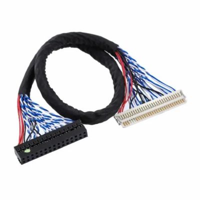
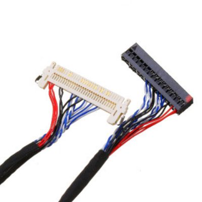
What LVDS Cable We Can Process?
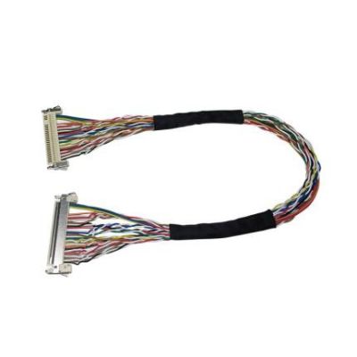
30 Pin LVDS cable
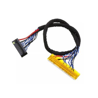
Fix 30PS8 Fix 30p Connector Lvds Cable
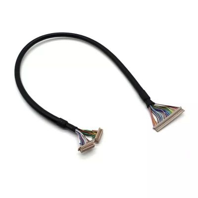
Hirose DF14 1.25mm LVDS Cable Assembly
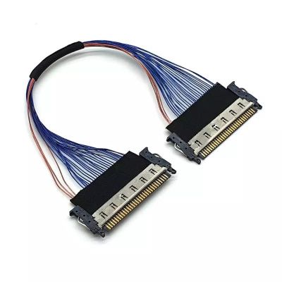
JAE FI-R 0.5mm LVDS Cable
LED LCD Display Panel Controller 30 Pin LVDS Cables
LVDS cable assembly
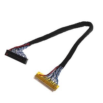
LVDS Cable FIX 30 Pin LCD LED Panel
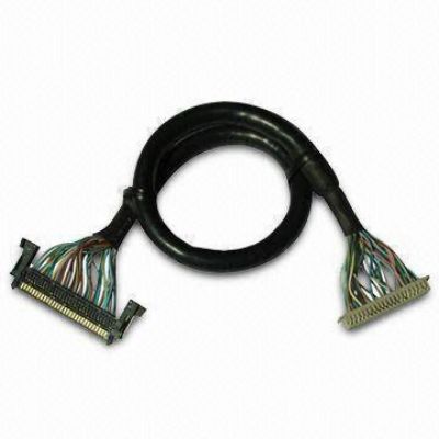
LVDS Cable
LVDS Cables
How to Customize Your LVDS Cable?
Send us your sample or drawing/schematic for quote price→ Feedback with quotation(1~3 days) → Confirm quotation → Arrange sample you for approval→ [Make mold if needed (7 days) →Mold test] → Making samples(1~3 days)→Samples test(Approval) →place order for Mass production(2~3 weeks)→Quality checking→Packing →Delivery →After Service →Repeat Order.
